Bottle flow
Infeed pressure, sensors, gates, indexing and outfeed release must keep containers stable and correctly pitched.

Bottle filling machinery
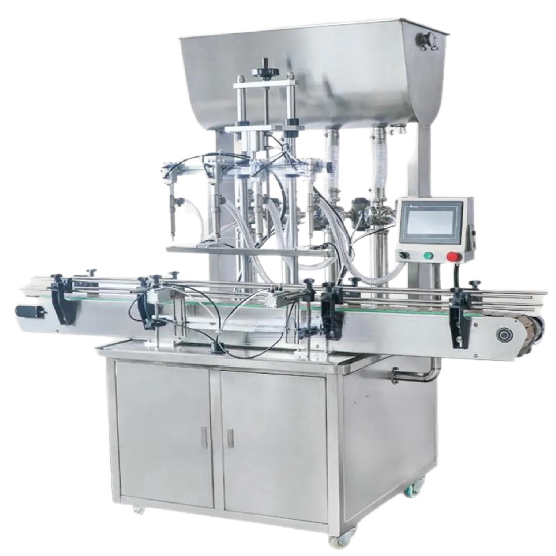
Conveyorised bottle filling equipment for repeatable production, using controlled bottle spacing, multi-nozzle dosing and interfaces for upstream and downstream machinery.
Application fit
The machine should be selected as a complete product-and-pack system, not from fill volume alone.
Specification priorities
The same nominal fill volume can require a very different solution when product behaviour, pack geometry or cleaning changes.
Infeed pressure, sensors, gates, indexing and outfeed release must keep containers stable and correctly pitched.
Head count, spacing, diving movement and anti-drip design are selected around bottle necks and product behaviour.
HMI recipes, counters, alarms and interlocks should match the wider line and the operator’s changeover process.
Power, compressed air, product feed, guarding, access and maintenance clearances should be agreed on a scaled layout.
Filling routes
Use the filling principle as a shortlist, then verify it with the actual formulation and representative bottles. Headline technology names do not replace product trials.
| Configuration | Practical role |
|---|---|
| Inline volumetric | Multiple piston cylinders or metering elements dose bottles indexed beneath the nozzle bank. |
| Automatic pump filling | Individually controlled pumps can support recipe changes and flexible liquid handling. |
| Servo dosing | Electronic motion or pump control provides repeatable recipes and synchronised filling cycles. |
| Integrated compact line | Filling, closure application and labelling can be arranged as a coordinated small-footprint system. |
Typical products
These examples indicate where the route may be considered; the actual product and container still need to be reviewed.
A potential application for automatic bottle fillers, subject to product and pack assessment.
A potential application for automatic bottle fillers, subject to product and pack assessment.
A potential application for automatic bottle fillers, subject to product and pack assessment.
A potential application for automatic bottle fillers, subject to product and pack assessment.
A potential application for automatic bottle fillers, subject to product and pack assessment.
A potential application for automatic bottle fillers, subject to product and pack assessment.
Project route
A structured review prevents the filler, bottle control and downstream machines from being specified in isolation.
Confirm viscosity, foam, particles, temperature, compatibility and cleaning.
Review bottles, necks, closures, labels and stability using representative samples.
Agree batch size, target rate, operators, changeovers and future growth.
Freeze layout, interfaces, utilities, guarding, tests, installation and training scope.
Related planning
Use these pages to compare adjacent machine routes and prepare a more accurate enquiry.
Measured positive-displacement dosing for liquids through to creams.
Explore Volumetric bottle fillers
Electronically controlled pump filling for compatible liquids.
Explore Gear pump bottle fillers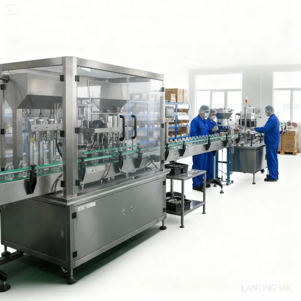
Connect bottle infeed, filling, closure and labelling.
Explore Complete filling linesQuestions
Practical answers for early project planning.
Provide product samples or data, fill range, bottle drawings or samples, closure details, target output, batch sizes, changeover expectations, available floor space and upstream/downstream scope.
Head count depends on the slowest fill time, indexing time and target bottles per minute. More heads are not automatically better if product supply, cleaning or changeover becomes impractical.
Yes in many projects, but line height, conveyor speed, electrical interfaces, accumulation and emergency-stop architecture must be assessed.
Not necessarily. A compact line may coordinate separate modules on conveyors, while a monoblock typically combines several operations around one main machine platform.
Lancing Ltd can compare the practical bottle filling routes and confirm the right next step before quotation.
Automatic container control
Automatic dosing depends on reliable bottle detection, spacing, indexing and release. The design must handle the least stable empty bottle, not only the easiest format, and must recover predictably after upstream or downstream interruptions.
Check how empty bottles arrive, accumulate and separate without wedging, scuffing or falling.
Confirm sensor targets, gate positions, pitch and the tolerance allowed before the nozzle descends or the dose starts.
Define what happens to bottles already under the nozzles after a stop, alarm, low product condition or downstream blockage.
These guides isolate the pack variables that can change an otherwise suitable filling-machine route.
Automatic bottle control
An automatic filler depends on a repeatable bottle journey as well as a repeatable dose. Empty containers must arrive in the correct spacing, locate under the nozzles, remain stable during filling and leave without carrying product onto the closure or label area. The acceptance plan should therefore test the control sequence around the fill, not only a continuous run after the machine has already settled.
Check the least stable empty bottle, gaps in bottle flow, bottle-present sensing, stop or gate timing and the response when an expected container is missing.
Confirm nozzle clearance, any diving movement, product cut-off, bottle support and the delay—if any—needed before the bottle transfers towards closure application.
Test restart after a planned stop, low product supply, bottle accumulation and a cleared fault. Record whether priming, rejects or operator intervention are needed before good production resumes.
| Scenario | Evidence to observe | Reason for inclusion |
|---|---|---|
| Cold start or first batch | Priming state, first accepted bottles and any product recovery or reject route | Shows how the line reaches controlled production |
| Normal bottle gap | No-bottle/no-fill response and correct nozzle or pump inhibition | Tests the real sensor and dosing interlock |
| Downstream blockage | Controlled stop, accumulation and restart without bottle contact or spill | Checks line communication rather than isolated filler speed |
| Format change | Mechanical changes, recipe selection, line clearance and first-off approval | Confirms the complete changeover task |
| Sustained production | Accepted quantity, presentation and good output under agreed conditions | Provides a repeatable comparison with the required production brief |
Use the fill accuracy and dose verification guide to define product condition, measurement method and sample points.
Use the bottle filling trials, FAT and SAT guide to document the scenarios that must be demonstrated.
Automatic-line readiness
An automatic filler should be assessed with product replenishment, bottle infeed, indexing, filling, outfeed and downstream stop logic operating together. Headline cycles do not show how the line behaves after a low-product condition, a blocked outfeed or a normal restart.
Confirm the capacity and buffering of bottle supply, capping, sealing, coding, labelling and packing interfaces.
Freeze layout, delivery access, utilities, product supply, safety interfaces and service access before delivery.
Open the installation guideInclude start-up, steady production, planned stop, blocked outfeed, replenishment, restart and format change in acceptance.
Open the acceptance guideAutomatic filling questions
Automatic operation depends on bottle detection, indexing, line signals and a repeatable restart sequence as well as the dosing hardware.
No-bottle-no-fill logic uses bottle detection and machine position to prevent a dispense command when the required container is absent. The exact coverage must be specified: detecting an empty station is different from confirming that a bottle is upright, correctly centred and suitable to receive the nozzle.
The trial should include missing, mis-spaced and deliberately stopped bottles without creating an unsafe test.
An automatic filler should enter a controlled state that prevents more bottles being released into a blocked discharge while protecting bottles already inside the filling cycle. The required stop, hold, drain, reject and restart behaviour depends on the product and line layout and should be written into the controls sequence.
A back-pressure signal alone is not the complete answer; the project must define what happens to partially processed and open bottles.
Potentially, if the line uses suitable pucks, nests, neck handling or other dedicated support. The support method must remain stable through infeed, filling, outfeed and any closure operation. It also becomes part of changeover, cleaning, reject handling and the spare-parts scope.
Provide the least stable production bottles and dimensional variation rather than relying only on drawings.
A recipe change should be followed by a documented first-off check covering the selected product and bottle, nozzle height and spacing, guides, fill setting, cut-off, bottle release and downstream presentation. Software values do not replace the mechanical checks or the need to confirm the first accepted bottles.
The restart sequence should define who approves the result and how rejected first-off bottles are controlled.
Verified automatic references
The model pages below do not replace a product trial. They show how published machine data is translated into bottle, product, output and line questions.
Six servo-driven magnetic-pump heads and a published 500–5000ml range.
Review LU-CL6TLifting nozzles and bottle detection for suitable automatic liquid applications.
Review LU-YT4T-4DCheck that product arrives at the filler under stable, clean and repeatable conditions.
Plan product supplyAutomatic line checks
Container stiffness, neck location, temperature, capping timing and accumulation can be as important as the filling principle once the operator is removed from the cycle.