Line engineering
Plan bottle flow before choosing individual machines
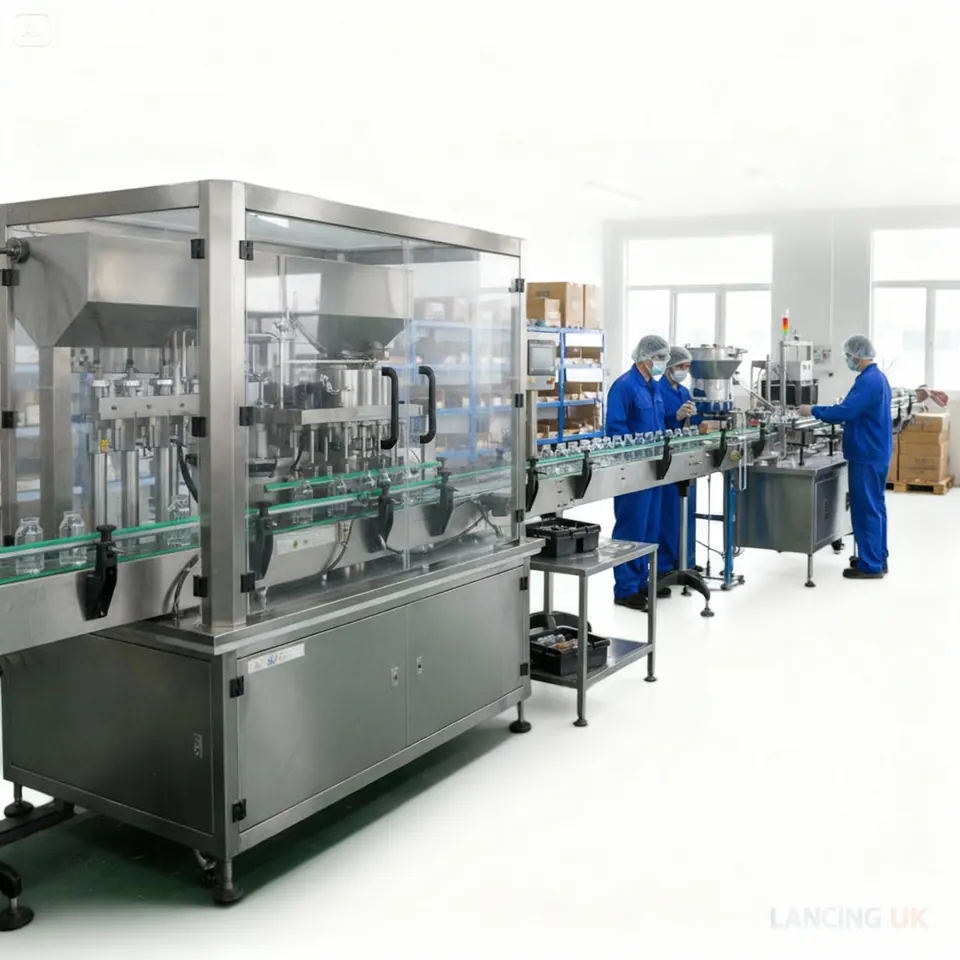
A filling line succeeds when bottles, closures, product and information move through the system at a controlled rate. Buying a fast filler without matching infeed, cap supply, labelling or pack-out can simply move the bottleneck.
Typical process sequence
Bottle infeed
Manual loading, turntable, unscrambler or depalletising establishes controlled bottle flow.
Preparation and fill
Rinsing or air cleaning where required, followed by sensing, indexing and dosing.
Close and seal
Plugs, caps, pumps, triggers or corks are fed, placed, tightened or sealed.
Identify and pack
Coding, labelling, inspection, accumulation and downstream packing complete the route.
Line planning checklist
| Workstream | Information to freeze |
|---|---|
| Product supply | Tank or hopper size, transfer pump, level control, temperature, mixing, return route and cleaning connection. |
| Bottle infeed | Bulk orientation, manual loading rate, minimum accumulation and bottle stability. |
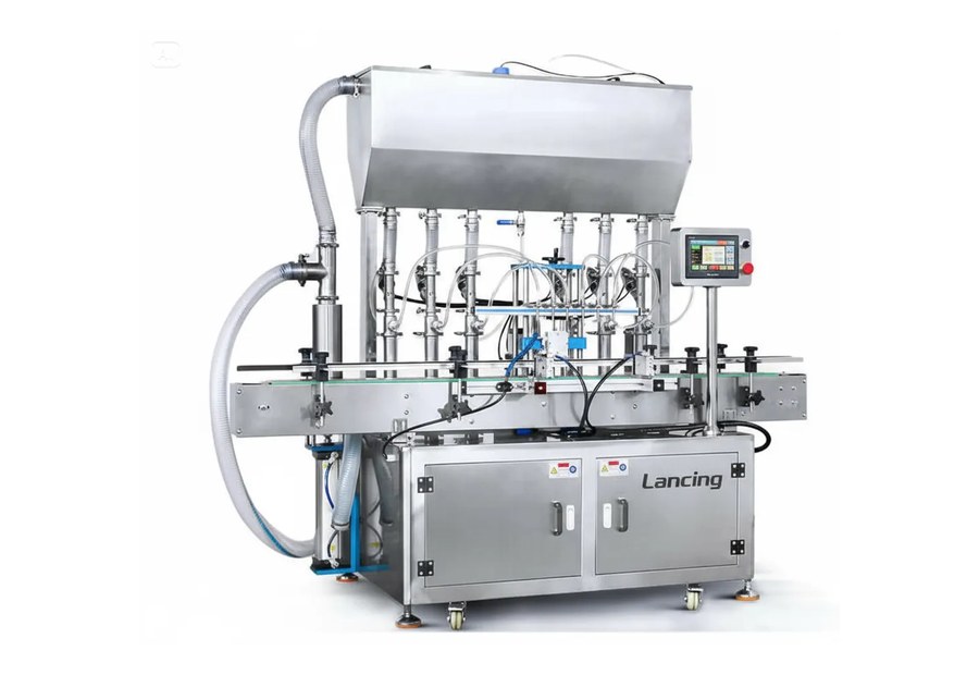
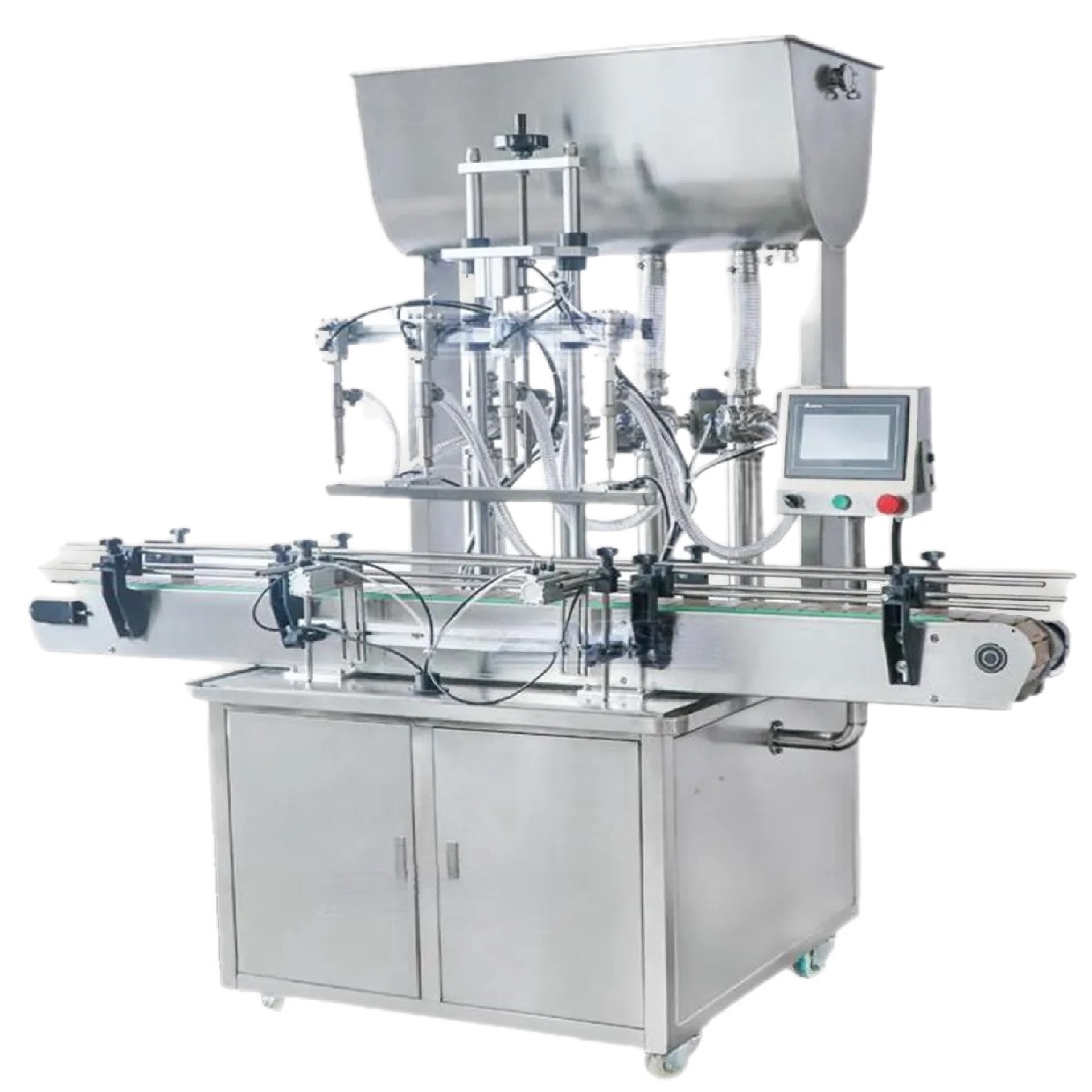
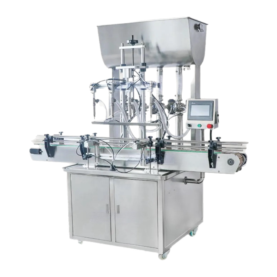
| Filling | Principle, head count, nozzle pitch, diving movement, fill range, recipes and verification. |
| Closures | Cap or pump family, feeder, orientation, insertion, torque, reject detection and replenishment. |
| Sealing | Induction foil, liner, leak test, tamper evidence and cooling or dwell requirements. |
| Coding and labelling | Code content, print technology, label orientation, inspection and reject handling. |
| Conveyors | Line height, width, speed, guide adjustment, transfer points, curves and accumulation. |
| Controls | Line master, speed reference, blocked/starved signals, emergency stops, alarms and data. |
| Safety and access | Guarding, doors, extraction, operator positions, maintenance clearances and material routes. |
| Acceptance | Products, packs, rate, run duration, tolerances, rejects, documentation and site test. |
Balance the machines using sustained rates
Each machine should have enough practical capacity to support the line rate after normal variation. A filler operating permanently at its absolute maximum leaves no recovery margin. Upstream and downstream modules may need different speed margins because their stop/restart behaviour differs.
Use blocked and starved logic
A machine is starved when it cannot run because no bottle or component arrives. It is blocked when it cannot discharge because the next stage is full or stopped. Defined signals let machines slow or stop in an orderly way instead of creating bottle pressure or spills.
Design changeover as a line activity
A saved filler recipe does not complete a changeover. The line may need guide, star-wheel, cap feeder, capping head, label and code changes. Document the sequence, tooling, settings and verification to avoid optimising one machine while the rest of the line waits.
Layout and utilities
- Scaled equipment footprint plus doors and access zones
- Operator replenishment paths and safe lifting heights
- Raw bottle, closure and label storage at the line
- Finished-pack and reject removal routes
- Electrical supply, compressed air, extraction, drainage and data points
- Product tank position, hose runs and cleaning access
- Forklift, pallet and maintenance access without entering guarded zones
Factory and site acceptance
Agree what will be tested before dispatch and what must be completed after installation. Define whether the trial uses production product or a substitute, how long the line must run, what counts as a stop, and how good output and fill tolerance are measured.
The integrator’s responsibility should be explicit. Interfaces that sit “between suppliers” are where line projects most often lose time.